Input Devices
This week's task was to measure something: add a sensor to a microcontroller board that you have designed and read it
To begin I took a deeper look to my final project and how my project should work.
So, my main idea was to develop a light sensing facade,so that the facade automatically sense the sunlight and rotate.
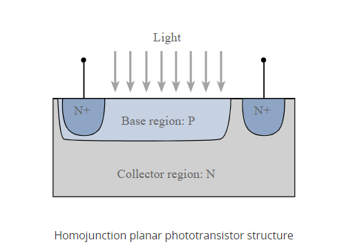
Phototransistor
Photo transistor is an electronic component which depends on the exposure to light to operate. A phototransistor will detect the light energy and convert it into digital electronic signals. It is capable of converting light energy into electric signals.
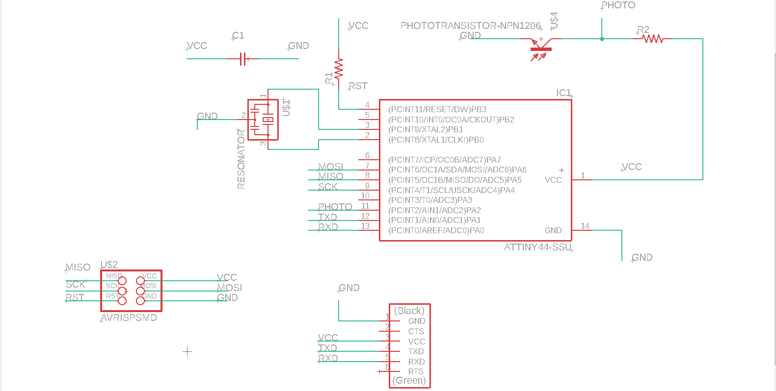
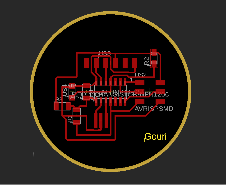
PCB Design
I started Design with ATtiny44 with Autodesk EAGLE. I learned a basic understanding of PCB design in ELECTRONICS DESIGN week-7.
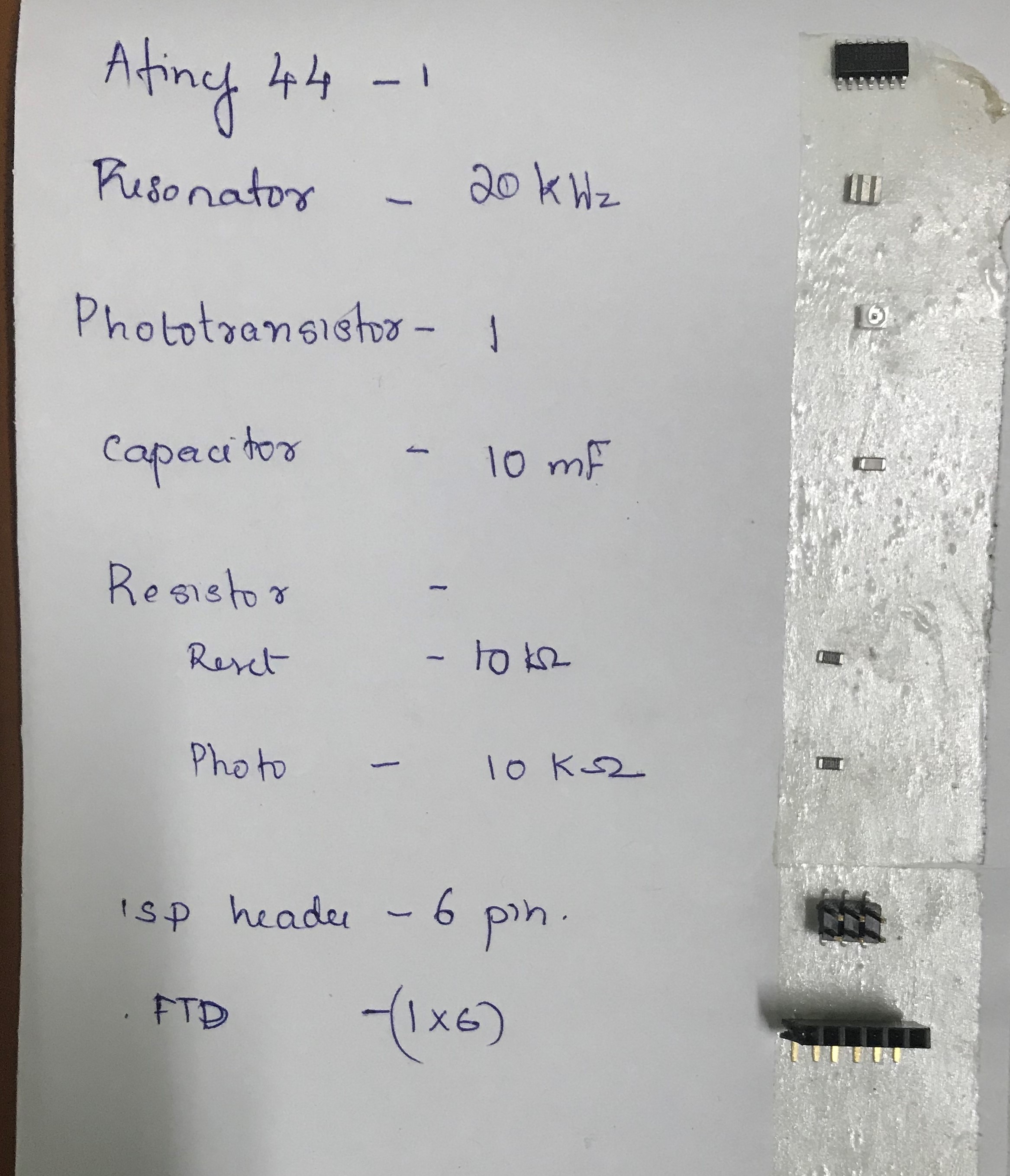
Components
ATtiny 44
20 KHz Resonator
Photo Sensor
10 K Ohm Resistor
10 μF capacitor
ISP header
FTDI header
Before routing the board, the most important step you have to do is set the Design rules. The design rules relate to the trace width, the clearance between the traces etc.
WE can open Design rules from the toolbar => Edit => Designing rules
Open the designing rules.
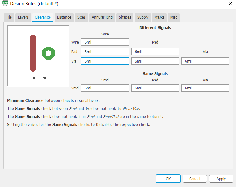
First we need to set the Clearnce , in default it' comes with the 6 mil in here fab we are using 1/64 bit for milling so here the trace will come around 16 mill.
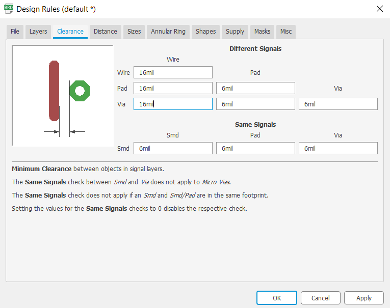
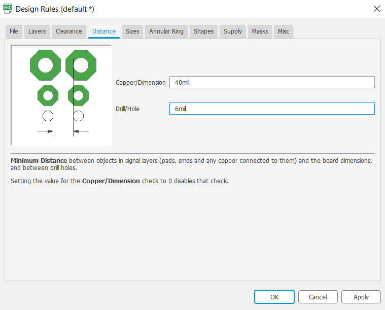
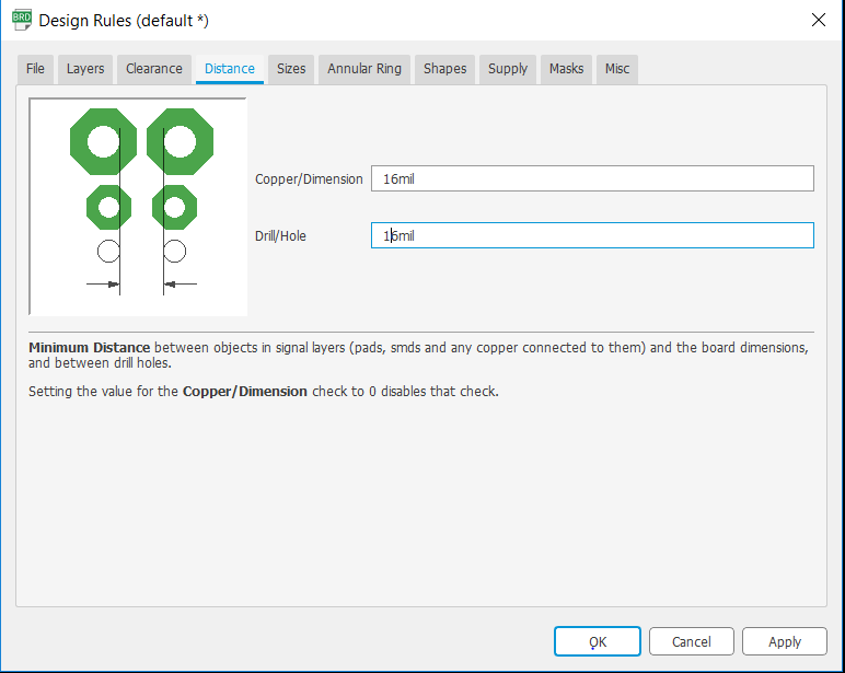
Next we need to take care the Distance ,it default value is 40 mil so in here i set the value to corresponding to our bit that is 16 mil.
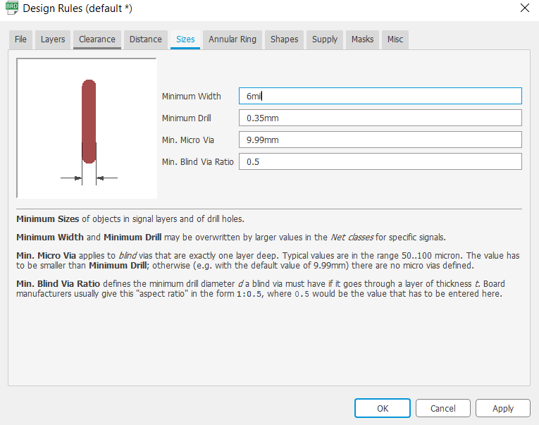
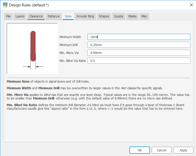
Next we need to set the Size of the Copper Trace , in dafult 6mil, and we need to make it 16 mil.
I used Autoroute Function in egale.
Mill trace
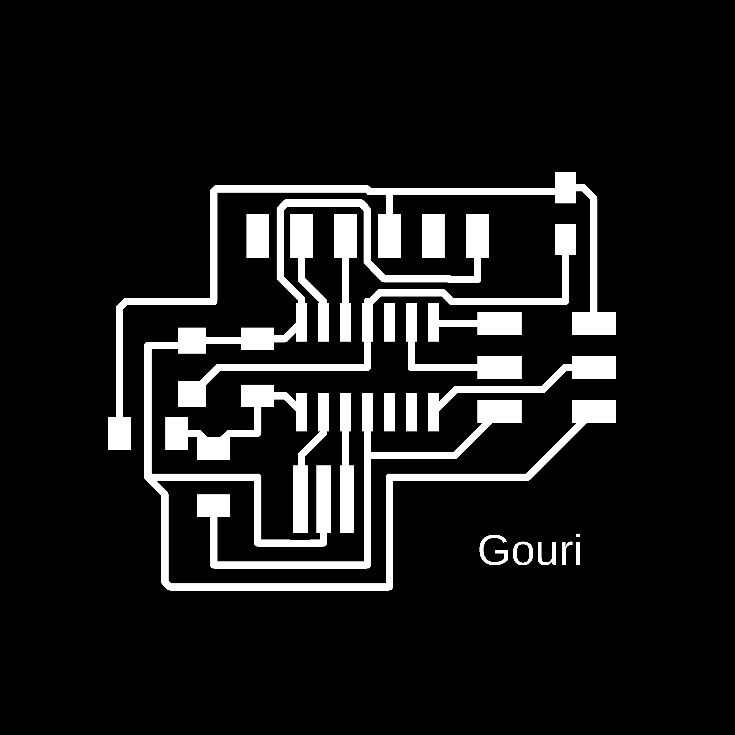
Cut trace

Components
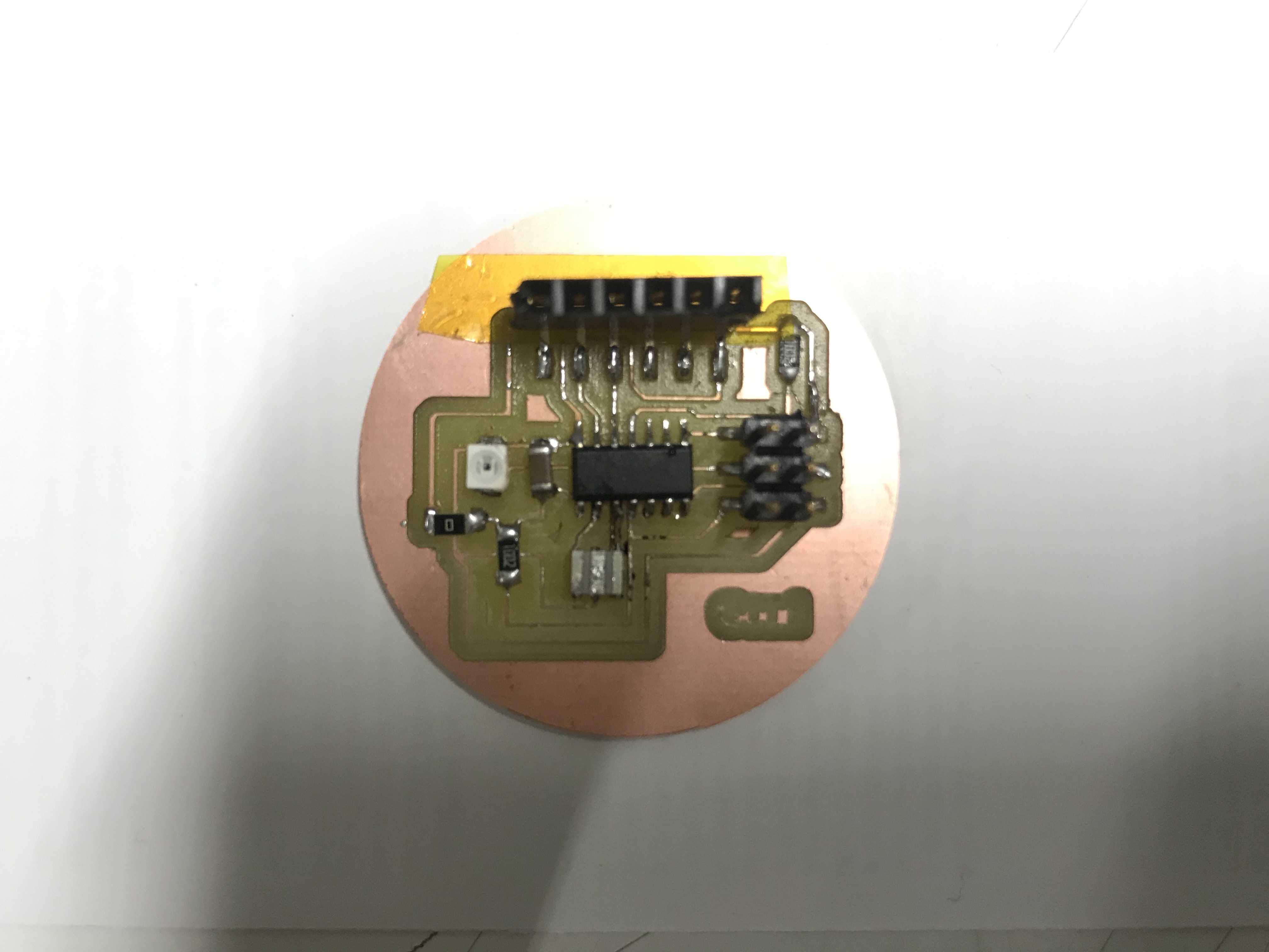
Soldered PCB
You can download the whole project from here.
ARDUINO CODE
                                    #include <SoftwareSerial.h>

                                    SoftwareSerial mySerial(1, 0); // RX, TX

                                    void setup() {

                                      mySerial.begin(9600);
                                      mySerial.println("Hello, world?");
                                      pinMode(A2, INPUT);
                                    }

                                    void loop() { // run over and over

                                      mySerial.println(analogRead(A2));
                                      delay(1000);
You can download the Arduino File from here.
DEMONSTRATION VIDEO
Group Assignment
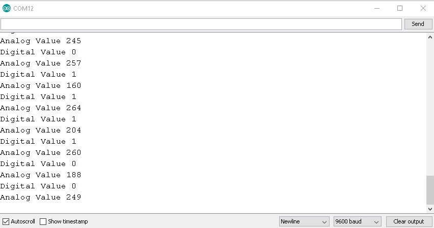
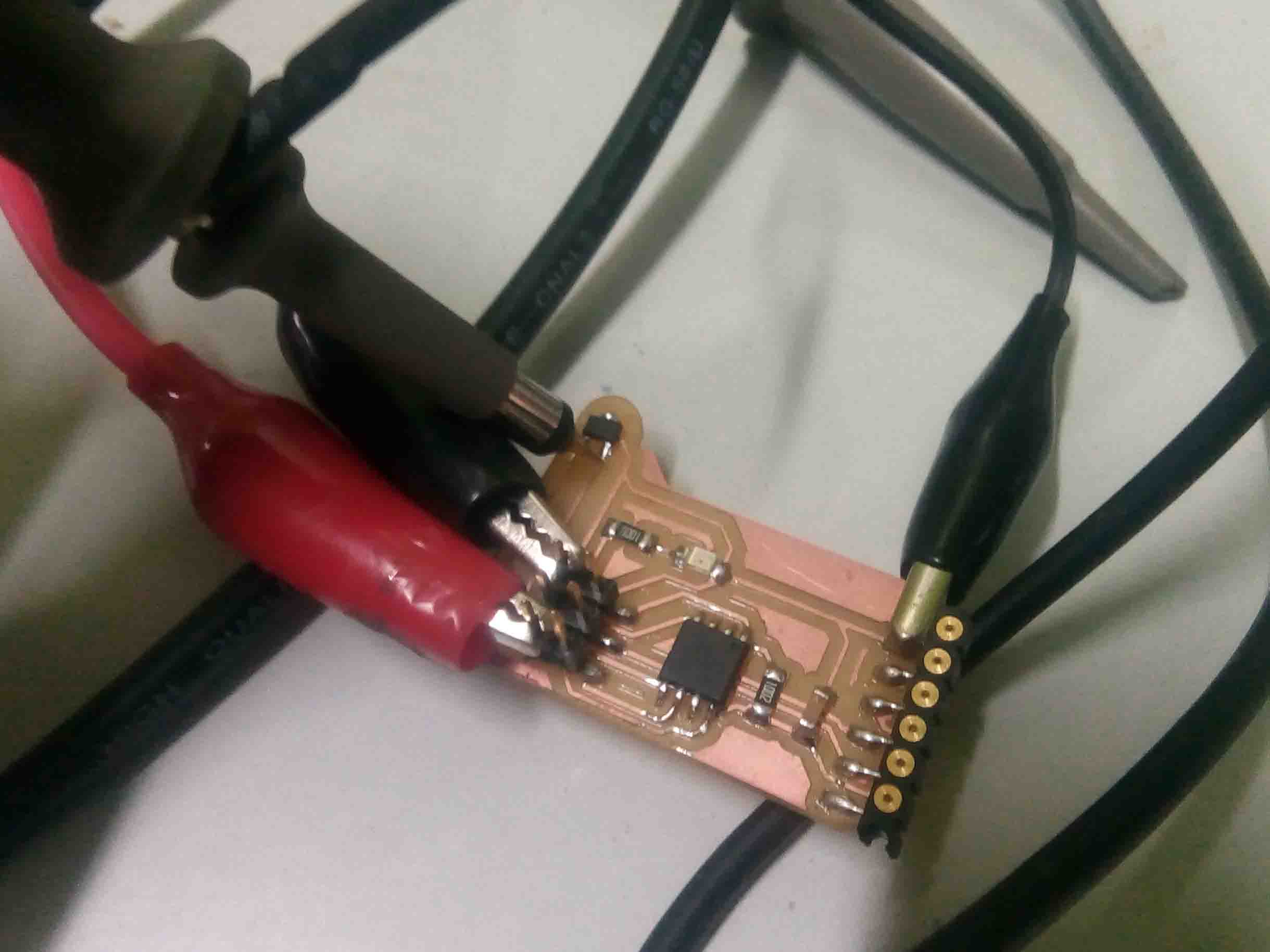
Probe an input device's analog levels and digital signals So I measured the the analog and digital values of the "Hall Effect Sensor". For that I upload the following code to ATtiny 45.
                            #include <SoftwareSerial.h>
                                       int sensorPin = 1;// hall effect sensor
                                       int digitalValue = 0;// variable to store the value coming from sensor
                                       int analogValue = 0;
                                       SoftwareSerial Serial(3, 4);
                                       void setup()
                                       {
                                        pinMode(sensorPin,INPUT_PULLUP);

                                        Serial.begin(9600); // initialize serial communications at 9600 bps

                                       }
                                       void loop()
                                       {
                                       digitalValue = digitalRead(sensorPin);
                                         analogValue= analogRead(sensorPin);
                                          Serial.print("Digital Value ");
                                        Serial.println(digitalValue); //print the value of sensor in digital
                                        delay(1000);
                                         Serial.print("Analog Value ");
                                        Serial.println(analogValue); //print the value of sensor in analog
                                        delay(1000);
                                       }
You can download the Group Assignment Arduino File from here.
The analog signals are varying when the magnet is bring closer to the sensor. The values are given below
I also confirmed the working using a DSO.
Here is the video..